![]() In the previous tutorial we looked at the modbus nodes and looked at how to read data from a Modbus server using node-red.
In the previous tutorial we looked at the modbus nodes and looked at how to read data from a Modbus server using node-red.
In this tutorial we will look at writing data to a modus server using node-red.
Writing Data
To write data we will use the modbus write node and modbus flex write node.
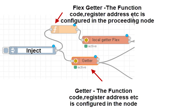
As we saw with the read nodes the write node has all of the configuration done in the node itself whereas the flex write gets the configuration from the preceding node.

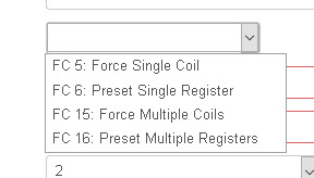
The nodes support the function codes 5,6,16,16 which allow you to write to coils,registers,multiple coils and multiple registers.

When writing we have the opposite problem of reading.
Modbus Write Examples
All of the examples use a flow like that shown below:

The function code is used to create the write command and the code shown in the examples is placed in this node. The inject node is used just to trigger the flow but it could also contain the value to write.
Write 16 Bit Integer
Again writing a 16 bit integer is easy as the node expects a 16 bit integer.
Below is the code from a function code that send a value of decimal 16001 to a modbus server using fc =6 (single register ) and start address of 40.
var fc=6;
var sa=40;
var addresses=1;
var value=16001;
msg.slave_ip="192.168.1.76";
msg.payload={"value":value , 'fc': fc, 'unitid': 1, 'address': sa , 'quantity': addresses };
return msg;
You should notice that I didn’t need to manipulate buffers.
Write 32 Bit Integer
However if we need to send a 32 bit integer then it is very different.
The code for the preceding function code is shown below were we write the value 16001 to address 50 using function code 16.The code is shown below:
var fc=16;
var sa=50;
var addresses=2;
var buf=Buffer.alloc(4);//create buffer
buf.writeInt32BE(68001);
var values=[(buf[0]*256+buf[1]),(buf[2]*256)+buf[3]]
msg.slave_ip="192.168.1.76";
msg.payload={"value":values , 'fc': fc, 'unitid': 1, 'address': sa , 'quantity': addresses };
return msg;
This time we use fc=16 for multiple registers and we need to use 2 registers.
32 bits =4*8(bits) which is 4 buffers and so we create our empty buffer.
We then write the integer (68001) into this buffer.
For multiple resisters the node expects 16 bit decimal values for each register and so we need to split our buffer into 2 parts.
We then create an array of the form [value1,value2].
Notice value1 is the low order 2 buffers (0,1), and value 2 is the higher order buffers (2,3). Notice also we need to multiple the buffers 1 and 2 by 256.
Write 32 Bit Float
The code for the preceding function code is shown below were we write the value 16001.5 to address 70 using function code 16.
var fc=16;
var sa=70;
var addresses=2;
var value=16001.5;
buf=Buffer.alloc(4);
buf.writeFloatBE(value);
//buf.writeFloatBE(16001.5);
var values=[(buf[0]*256+buf[1]),(buf[2]*256)+buf[3]]
msg.slave_ip="192.168.1.31";
msg.payload={"value":values , 'fc': fc, 'unitid': 1, 'address': sa , 'quantity': addresses };
return msg;
You should notice it is almost identical to the 32bit integer.
Write 64Bit Float
The code for the preceding function code is shown below were we write the value 16001.5 to address 80 using function code 16. Because it is 64 bits we need 8 buffers.
var fc=16;
var sa=80;
var addresses=4;
var value=16001.5;
buf=Buffer.alloc(8);
buf.writeDoubleBE(value);
//buf.writeFloatBE(16001.5);
var values=[(buf[0]*256+buf[1]),(buf[2]*256)+buf[3],(buf[4]*256+buf[5]),(buf[6]*256)+buf[7]];
msg.slave_ip="192.168.1.76";
msg.payload={"value":values , 'fc': fc, 'unitid': 1, 'address': sa , 'quantity': addresses };
return msg;
Signed and Unsigned
All of the examples given above use signed integers. If you need to write unsigned use writeUInt16BE() and writeUInt32BE().
BE and LE
All of the examples above use BE format. If you need LE format replace BE with LE.
I.e writeUInt16BE() becomes writeUInt16LE() etc
Video Writing data to Modbus
Resources
Flow for video1,video2 and dashboard
Using The TCP Node
A reader recently came across a problem resetting a PZEM 017 . The documentation gave the code as fc=66:
below is part of the data package:
| Part of Data Package | Description | Value |
| 01 | Slave address | 0x01 (1) |
| 42 | Function code | 0x42 (66) |
| 80 11 | Data | |
| 00 00 | CRC | 0x0000 (0) |
He was able to reset it using modbus poll but not with the modbus flex write because it doesn’t support function code 66.
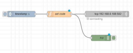
We were able to achieve the same result using the TCP node.

Th function node code is:
msg.payload=Buffer.from([0x01,0x42,0x80,0x11]);
return msg;
Notice we needed to create a buffer from the data just using an array doesn’t work.
–>Modbus Node-Red Dashboards and MQTT Modbus Bridge
Related Tutorials
- Modbus Node-Red Dashboards and MQTT Modbus Bridge
- How to Use Node-Red with Modbus
- My Modbus Working Notes


Hi Steve,
No need to reply to the previous message.
I have now found what the address field refers to. It is the register address for the selected function code.
I was really mixing this up with either IP or RTU addressing, however it has nothing to do with that.
Thanks again.
Regards,
Dan
Hi Steve,
Within the the Modbus read and write nodes properties setting there is an address field. Can you please specify what this represents?
Currently I am using OpenPLC and Node-Red in a VM and gaining access via my host machine using port forwarding. So therefore I have set OpenPLC’ IP address as the server. I have created a user interface and can switch buttons on/off on the ui, however to do this I must match the address within the Modbus read/write nodes with the I/O addresses of the PLC.
As I understand it, Node-Red is communicating with the OpenPLC via Modbus TCP/IP. I do not have specific IP addresses for the slave devices, just the addresses that match the I/O numbering of the PLC.
I am wondering if the address field represents Modbus RTU, as I know they require a specific address which is contained in the PDU. And as I have mentioned none of my external slaves have an IP.
I have tried to find clarification of this high and low but nothing definitive I have been able to locate.
My system is working, but if I change the addresses in the Modbus read/write nodes so they do not match the PLC it stops working.
Can you confirm or deny that perhaps my situation is using Modbus RTU and the address fields represent this?
Apologies for the story, however I am hoping you can clarify.
Regards,
Dan
Hi – Steve
typo at
Signed and Unsigned
All of the examples given above use signed integers. If you need to write signed use writeUInt16BE() and writeUInt32BE().
If you need to write signed =>> If you need to write Unsigned
Hi
Tks for that I have corrected it.
Rgds
Steve
Hi
I’m new for node red I have some doubts mention below kindly any one help
1. I’m reading distance sensor in my node red now I want to send that sensor data to HMI through TCP/IP protocol how can i do this ( I want to send multiple data )
You just pass the data into the tcp-out node.
Rgds
Steve
sorry I cant understand
Hello. I ran into a problem, please help me find a solution.
There is a two-channel relay with Modbus, I use the package to communicate with it node-red-contrib-modbus
Read channel 1 and channel 2 state :01 03 00 01 00 02 95 CB — it is not problem
The problem starts when I initiate the write, namely
The command to turn on, according to the manual, looks like 01 06 00 01 01 00 D9 9A
That is, to turn on the channel ‘1’ relay, it is necessary to write the value 0x0001 to the register at address 0x01.
Now the actual question
How to write data to a register using LE bit order using node modbus-flex-getter?
Are you using 16bit registers?
Have you tried the code in the tutorial and the flow
var fc=6;
var sa=40;
var addresses=1;
var value=16001;
msg.slave_ip=”192.168.1.76″;
msg.payload={“value”:value , ‘fc’: fc, ‘unitid’: 1, ‘address’: sa , ‘quantity’: addresses };
return msg;
and changing the sa to 1 and the value to 1?
rgds
steve
rgds
steve
I have successfully been able to read modbus IP/TCP just via the ‘modbus read’ function.
However I struggle to write to the DO part of the IO-board.
The modbus IO is a iSMA-b-mix 38, I write to it via the ‘modbus write’ function.
There’s 12 DO’s and I write to them via 1, for DO1. 2, for DO2. 4, for DO3 and all the way up to 2048 for DO12.
The relays react but only stays on for 500ms to 1sec.
Is there an easy way to get them to stay on all the time?
If they react then the write is working maybe there is a setting that determines if they only flip or they stay on?
rgds
steve
Hi,
I wonder how to pass a negative values to my PLC with modbus tcp, I need to send an offset for a regulator that can be both positve and negative value.
any ide?
The buffer write will write unsigned and signed values so just use the signed values which is what I have used in all my flow examples they look like this
buf.writeIntBE16
and not like this
buf.writeUIntBE16
Rgds steve
This is just above my competence level to understand.
I’ve tried to write the value “-5000” to a register (init16) using buffer maker and buffer parser. Without success, hence ending here to see if I could understand this – still cannot.
Reading via modbus and writing positive values is working fine. I justt cannot send negative value “-5000” equivalent to “-50%) to my inverter
How would input-, function- node look like if I used FC16(or FC6) and eg. modbus flex writer?
I’m even willing to pay for the solution – I’ve spent hour and hours to get this to work.
Thanks in advance,
Peter
Also posted this ttopic with the details in it:
https://discourse.nodered.org/t/writing-negative-value-to-register-via-modbus-tcp-ip/58976
Hi Steve,
Great guide!!
Can you help me with my problem?
I want to reset a counter on a PZEM-017. I have connected it over Modbus TCP. It is already working with Node Red.
One thing is missing. The reset of the counted energy.
I know the reset code but I dont know how to put it in the right form.
# 0x01 Slave address
# 0x42 Magic code
# 0x80 CRC for slave address (0x01)
# 0x11 CRC for magic code (0x42)
data = [0x01, 0x42, 0x80, 0x11]
Can you help me please?
Greatings
Stefano
Hi
sent email requesting flow
rgds
steve
Hello, could you share the mentioned flow? It would be very useful.
Best regards,
Edd
There is a download link in the tutorial are you tried it if so is there a problem so I can correct it.
Here are direct links to all my modbus flows
https://stevesnoderedguide.com/download/modbus-video1
https://stevesnoderedguide.com/download/modbus-video2
https://stevesnoderedguide.com/download/node-red-modbus-and-mqtt-dashboard-video-3
https://stevesnoderedguide.com/download/modbus-mqtt-dashboard
rgds
steve
Hi Steve,
thank you for your usefull guide.
I’m using the node “modbus-flex-write” to write 16 holding register (addr: 40001) but I get this error: “TypeError: Cannot read property ‘getMachineState’ of undefined at Object._inputCallback (/opt/node-red/node_modules/node-red-contrib-modbus/modbus/maps/modbus-flex-write.js:52:5) at Object.Node._emitInput (/opt/node-red/node_modules/@node-red/runtime/lib/nodes/Node.js:199:18) at Immediate._onImmediate (/opt/node-red/node_modules/@node-red/runtime/lib/nodes/Node.js:179:33) at processImmediate (internal/timers.js:439:21)”
I really don’t know to root cause of this error. Didi you ever see this type of error?
Thanks for your time!
Best regards,
Federico
No Never seen it before. What version of node-red and nodejs are you using?
Rgds
Steve