
In this tutorial we are going to look at using the node-red-contrib-bool-gate module which provides four basic boolean logic functions.
If you are unfamiliar with logic gate operation the first section covers the logic gates and the second covers using the logic gates in node-red flows.
Logic Gates Overview
A logic gate is the fundamental building block of digital circuits. It performs a basic logical operation on one or more binary inputs to produce a single binary output.
The behaviour of a logic gate is defined by a Truth Table, which lists all possible input combinations and their corresponding output.
There are seven basic types of logic gates and in electronic circuits each gate has a particular symbol.
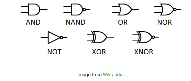
The Seven Basic Logic Gates
The first three are the simplest, and the others are often built from them.
- NOT
- AND
- OR
- NAND
- NOR
- XOR
- XNOR
1. NOT Gate (Inverter)
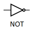 Function: Reverses the input.
Inputs: 1
Boolean Expression: Result = A̅ (pronounced “Result equals NOT A”)
Truth Table:
A Result
0 1
1 0
2. AND Gate
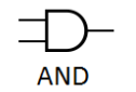 Function: Outputs 1 only if ALL of its inputs are 1.
Inputs: 2 or more
Boolean Expression: Result = A · B or Result = AB
Truth Table:
A B Result
0 0 0
0 1 0
1 0 0
1 1 1
3. OR Gate
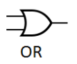 Function: Outputs 1 if AT LEAST ONE of its inputs is 1.
Inputs: 2 or more
Boolean Expression: Result = A + B
Truth Table:
A B Result
0 0 0
0 1 1
1 0 1
1 1 1
4. NAND Gate (NOT-AND)
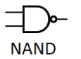 Function: The opposite of an AND gate. Outputs 0 only if ALL inputs are 1. It’s a universal gate.
Inputs: 2 or more
Boolean Expression: Result = A · B (with a bar over the whole A·B)
Truth Table:
A B Result
0 0 1
0 1 1
1 0 1
1 1 0
5. NOR Gate (NOT-OR)
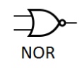 Function: The opposite of an OR gate. Outputs 1 only if ALL inputs are 0. It’s also a universal gate.
Inputs: 2 or more
Boolean Expression: Result = A + B (with a bar over the whole A+B)
Truth Table:
A B Result
0 0 1
0 1 0
1 0 0
1 1 0
6. XOR Gate (Exclusive-OR)
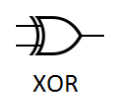 Function: Outputs 1 if the inputs are DIFFERENT. “Either A or B, but not both.”
Inputs: 2 (typically)
Boolean Expression: Result = A ⊕ B
Truth Table:
A B Result
0 0 0
0 1 1
1 0 1
1 1 0
7. XNOR Gate (Exclusive-NOR)
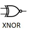 Function: The opposite of an XOR gate. Outputs 1 if the inputs are the SAME.
Inputs: 2 (typically)
Boolean Expression: Result = A ⊙ B or Result = A ⊕ B (with a bar over it)
Truth Table:
A B Result
0 0 1
0 1 0
1 0 0
1 1 1
Node-RED logic Gates –node-red-contrib-bool-gate Module
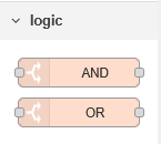 As stated previously the module which provides four basic boolean logic functions using two nodes.
The AND node provides the AND and NAND functions and the OR node provides the OR and NOR functions.
Using The AND Node
This is probably the simpliest node to understand. It produces a true output when all inputs are true otherwise it is false.
In electronic circuits we have a different input wire but it the node the inputs wires are the topics.
A demo flow is shown below:
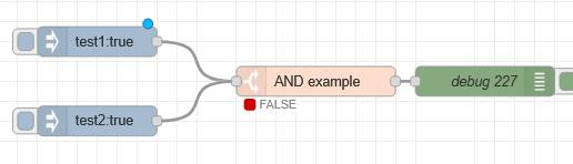
The important thing to understand is that the topics for the inject are set to test1 and test 2 and both inject nodes will send in a boolean of true.
the And node is configured as shown below in fig 1:
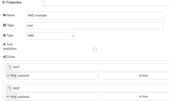
Notice the rules.
The first rule is
topic test1 payload =true
the second rule
topic test2 payload =true
So with our inject nodes configured as described above we should get a true output as shown below:
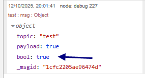
Notice the output is on the msg property bool.
We can have more than two inputs by adding additional rules with different topics.
However we must have at least two rules.
In electronic circuits we test for true/false or 1/0.
However in out flow we could test for input strings,numbers etc.
In the next example we will use the inject nodes to inject a number which we set to 20 for both inject nodes.
The and node configuration is shown below in fig 2
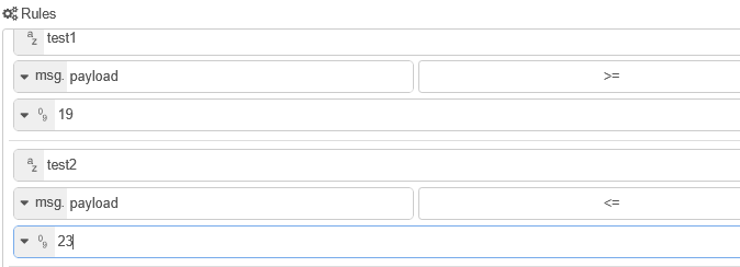
What do you expect the output to be ?
If we change the rule for test 1 to be 21 what do you expect the output to be?
Answers:
true and false.
Note1: for the node to do the and function you need to inject both test1 and test2.
Note2: The node remembers the last input for each topic.
Note3: there is a check box marked true restriction which means that the node will only send an output when it is true.
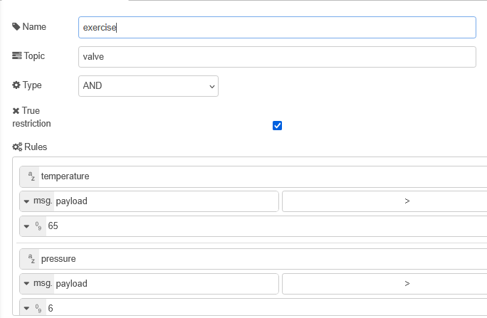
Worked example:
We have an overflow valve that needs to activate when the temperature exceeds 65 C and the pressure exceeds 6 bar. the value requires a payload of true on the topic valve.
Our temperature reading uses the topic temperature and our pressure reading uses the topic pressure. Both are numbers (no units).
What gate do we need and what is the configuration.
Answer:
We need an AND gate with the following configuration:
Video-
Rather than show endless screen shots I will cover the AND and OR nodes in the following video which I hope should make it easier to understand and use.
demo flow used in video

Related tutorials and resources:
- Using the Node Red Status Node
- Node-Red HTTP Request Node for Beginners
- Using the Node-Red Function Node- Beginners Guide